Précautions, électricité statique

Electrostatic Sensitive Devices (ESD)
Field Effect Transistors (FET) in this module can be destroyed by static discharges.
- Take applicable precautions:
- Always touch chassis first, before touching anything inside the module.
- Ensure your soldering station is "ESD safe".
Noter la position du fourneau
Photo #1
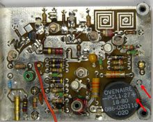
Note the positionning of the crystal oven
- This oven is a polarized device.
- Note the markings on the oven and on the board.
Retirer le fourneau
Photo #2
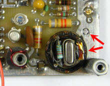
Pull-out the oven
- Look under the board to ascertain the oven and crystal are merely plugged-in (rather than soldered).
- Pull the oven up so as to expose the crystal.
- It is very likely that the cap will come off the oven base because the glue has totally cooked over time.
Remplacer le cristal
Photo #3

Replace the crystal
- Trim the crystal leads and "sandwich" a Mylar® insulator between the crystal and the board.
- The insulator prevents the crystal metal casing from touching traces on the board.
- The insulator must withstand the 80 °C temperature of the oven.
Remettre le fourneau en place
Photo #4
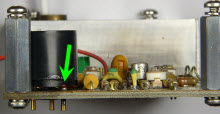
Position the oven over the new crystal
- Again, note the red dot on the side of the oven.
- Ensure it is on the side of the "positive" marking on the board.
- Use Contact Cement to glue the oven cap if it came unglued.
Syntonisation
Photo #5
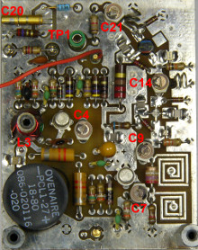
Tune-up
- See written instructions for details: capacitors can be preset to documented positions.
- The ability to measure level and frequency at 90 MHz and 180 MHz is a plus.
- Output frequency is 2160 MHz ( 90 × 2 × 2 × 6 ).
- Final frequency tuning will only be done after a 3 to 4-day burn-in period.
Syntonisation du doubleur
Photo #6
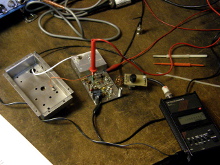
Photo #7
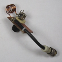
Sniffing the second harmonic
- A preselector on the input of the frequency counter may be useful.
- The one shown tunes from about 135 to 235 MHz.
Si vous n'avez pas de splitter...
Photo #8
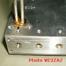
Photo #9
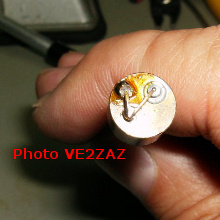
Alternative to splitter, provide second LO output
- If you did not obtain a splitter, this is "Plan B":
- Note the position of the brass output slug and pull it out.
- Drill a hole through it for a new (teflon core) coaxial cable.
- Shape a coupling loop next to the original one.
- Use the original output for TX and the added output for RX.
Thanks to Bertrand VE2ZAZ for sharing his expertise, experiment and pictures.