Régulateurs (2×)
Photo #
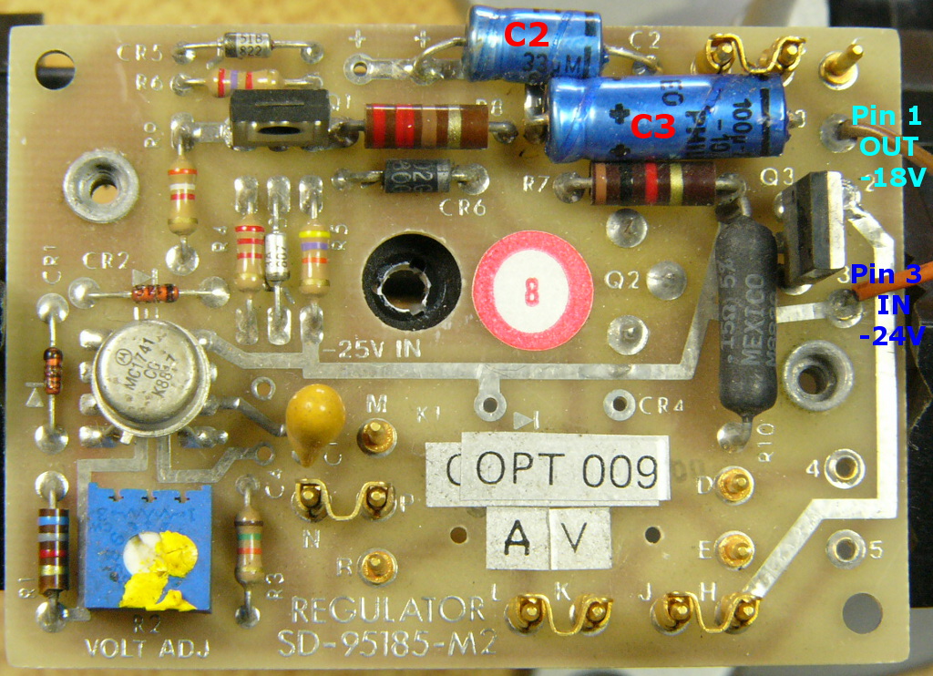
Regulators (2×)
Save mica insulator and plastic insulator for later re-install.
Test for regulation, with and without load (≈ 1A).
Correct any high-frequency oscillation on DC output (faulty capacitors, C2 or C3).
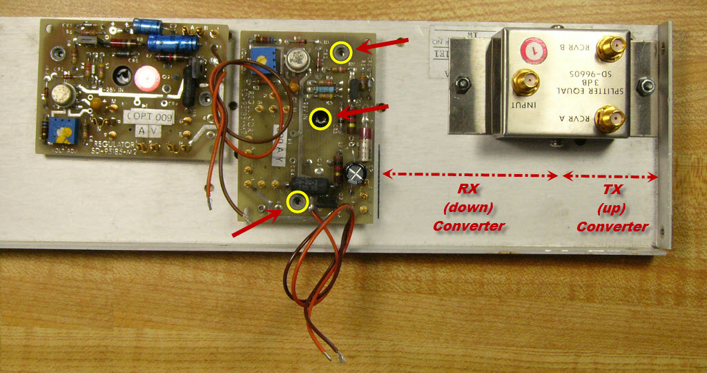
Mélangeur-abaisseur (RX)
Photo #

Position Down-Converter (RX)
Drill and tap, three places.
Noyaux d'accord (Oscillateur Local)
Photo #


LO tuning slugs ( 3× )
Solder extension to slugs.
Shims are used on the jig to center the extension on the end of the slug.
A blow torch is used to heat the material.
First, deposit a dab of solder on the end of the slug.
Slug must be kept clean and round so it rotates precisely within the resonator cavity.
Avoid heavy filing which may alter the uniformity of the slug.
Montage des régulateurs et du diviseur
Photo #
Mount regulators and splitter
Be sure to use mica insulator, plastic insulator and heat-transfer compound on final assembly.
Panneau frontal
Photo #
Prepare front panel
- Power switch (12 VDC).
- Light Emitting Diodes:
- Power ON.
- TX.
- RF Out.
Panneau arrière
Photo #

Prepare back panel
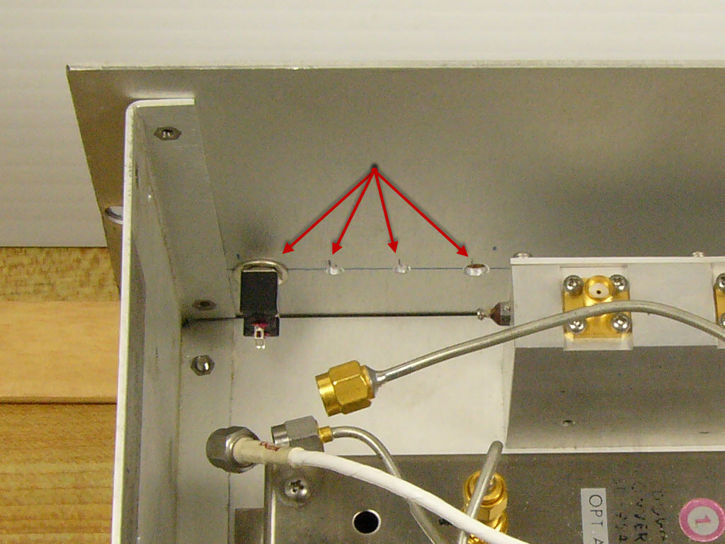
Trous de fixation de la plaquette
Photo #
Determine hole locations for board
Do before assembly, because one relay is fitted under board.
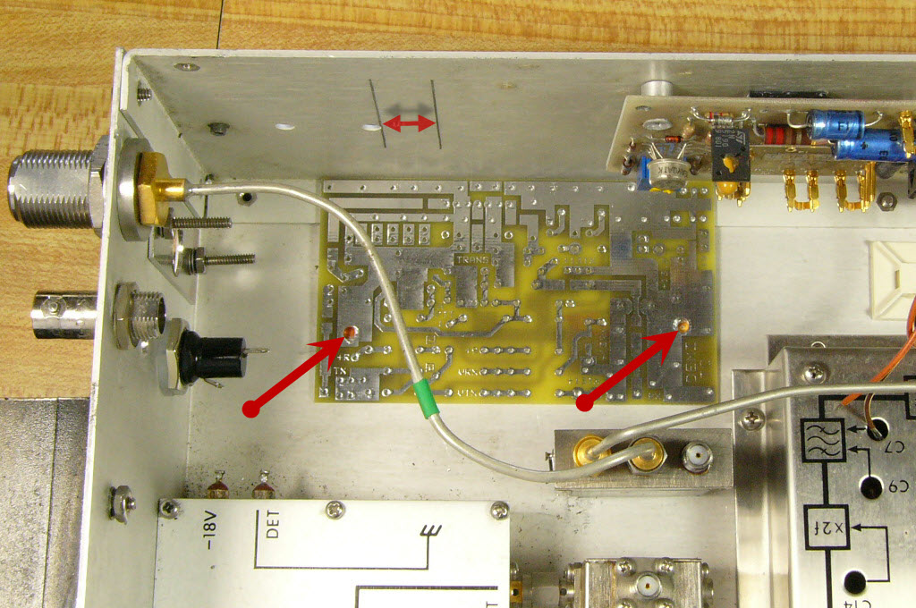
Réutilisation du coaxial le plus long
Photo #
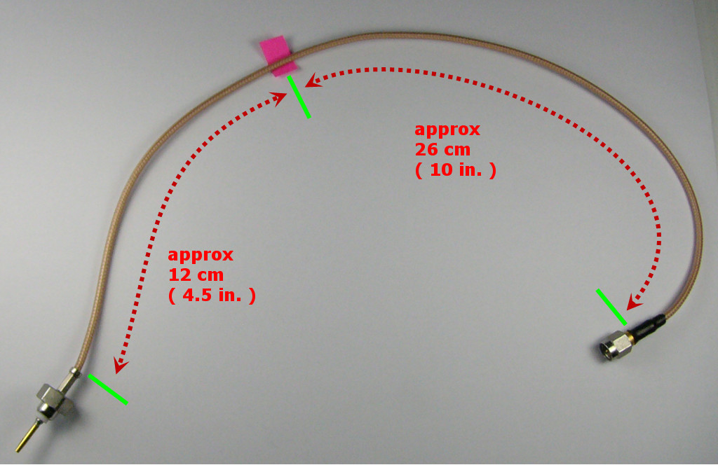
Cut longest coaxial in 2 parts
- 144 MHz <-> Transceiver terminal, TC board.
- RX terminal, TC board <-> Down-Converter.
Cut carefully so both sections can be effectively re-used.
Plaquette d'interface DEMI
Photo #
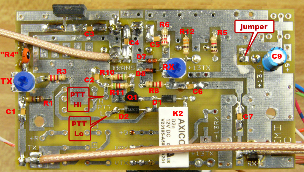
Assemble DEMI interface board
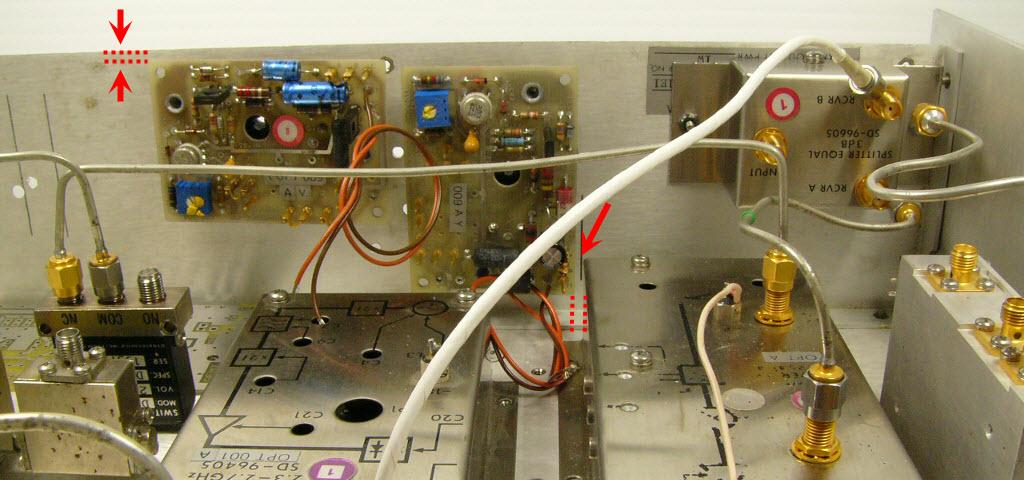
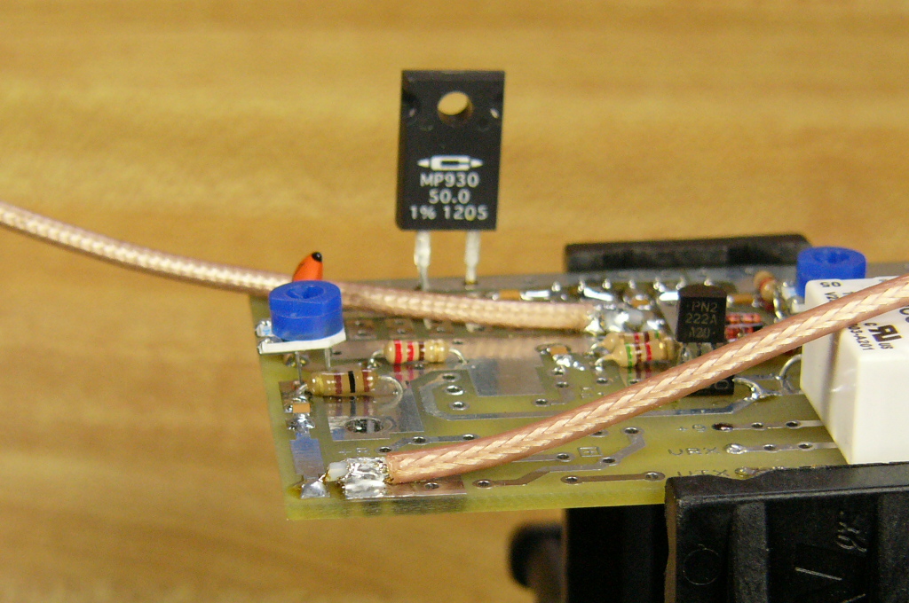
Mise en place de la plaquette
Photo #
Mount interface on stand-offs
Metallic stand-offs ensure ground connection.
Attach dummy load to side panel. Use heat-transfer compound.
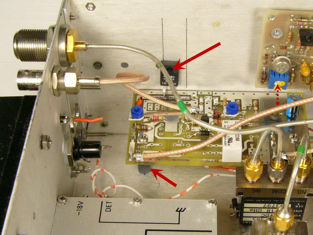
Lien semi-rigide en forme de "U"
Photo #
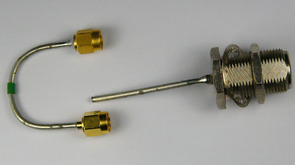
Photo #
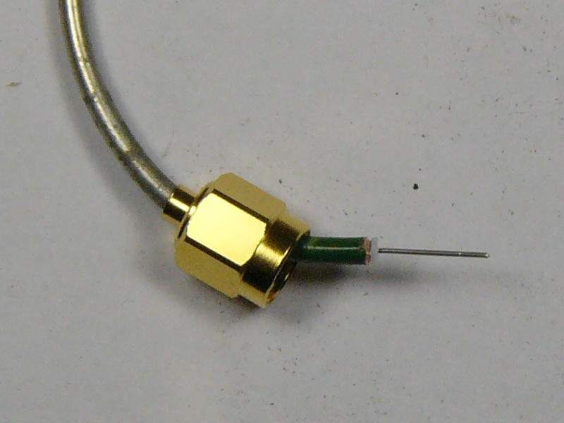
Prepare short U-shaped coaxial jumper
Cut one of the lines formerly attached to the back panel. Solder SMA connector.
Used between PA and T/R relay.
Be sure to insert small Teflon® spacer before soldering centre pin.
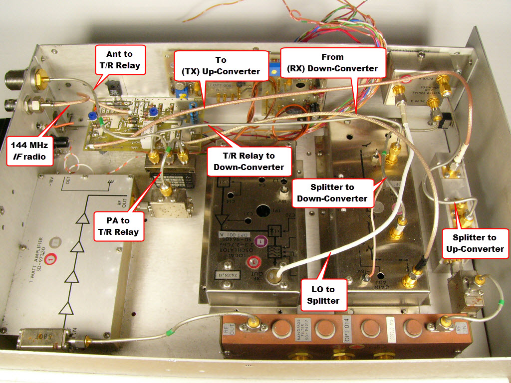
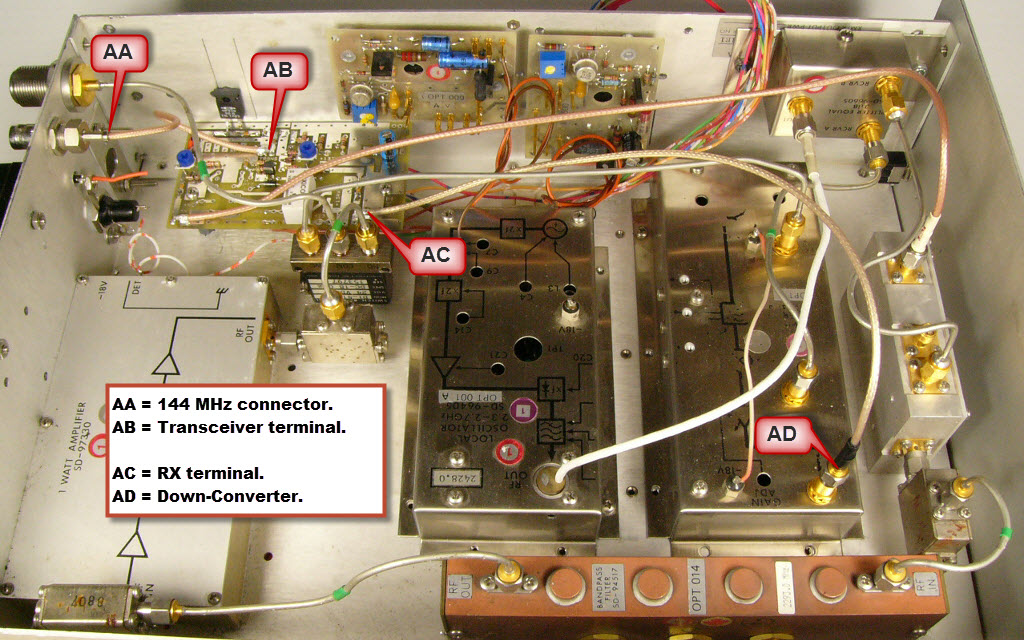
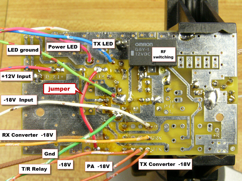
Raccordements RF
Photo #